How Can You Select an Industrial Hose for Oil and Fuel Transfer?
An industrial hose for oil and fuel transfer should be selected from the actual fluid, pressure, vacuum, temperature, flow rate, installation, and coupling data rather than from diameter alone. Gasoline with 10% ethanol can behave differently from straight petroleum fuel, while B20 diesel may contain up to 20% biodiesel. A 50 mm hose moving 300 L/min also faces different velocity and pressure loss from a 25 mm line at the same flow. Check the tube compound, working pressure, suction rating, electrical properties, minimum bend radius, cover resistance, and fitting rating together. The complete hose assembly can only be rated as high as its lowest-rated component.
The fluid comes first because “oil resistant” does not describe one chemical condition. Diesel, gasoline, kerosene, mineral oil, hydraulic oil, heating oil, synthetic lubricants, ethanol blends, and biodiesel blends place different demands on elastomers. E10 contains about 10% ethanol, while B20 commonly contains 6% to 20% biodiesel under ASTM fuel classifications. Alcohol and biodiesel content can increase swelling or extraction of additives in compounds that were originally designed around conventional petroleum fuel.
For that reason, the supplier should receive the exact fuel name, blend level, expected contaminants, and maximum exposure temperature before a tube compound is approved. NBR, often called nitrile rubber, is widely used for petroleum service because it has good resistance to many oils and hydrocarbon fuels, but “NBR” alone is not a specification: acrylonitrile content, plasticizers, cure system, and compound formulation change performance.
A hose carrying E0 gasoline for 30 minutes per week does not have the same exposure as a hose carrying E10 continuously for 8 hours a day, even when both are described as gasoline service.
Once chemical compatibility is established, pressure becomes the next filter. Normal pump pressure is not enough. Valve closure, pump startup, elevation changes, and flow restriction can produce short pressure peaks above the steady reading. A system operating at 10 bar may occasionally see 12–15 bar, so the hose, coupling, gasket, and attachment method must all be checked against the highest expected condition rather than the average gauge reading.
SAE J517, revised in 2020, states that the maximum working pressure of a hydraulic hose assembly cannot exceed the lower working-pressure rating of the hose or its connectors. The same engineering approach is useful in fuel-transfer assemblies: a 20-bar hose fitted with a 10-bar coupling is a 10-bar assembly for rating purposes, not a 20-bar one.
| Application data | What should be verified |
|---|---|
| Normal pressure | Continuous hose and fitting rating |
| Maximum pressure | Pump and valve operating extremes |
| Pressure surges | Short transient conditions |
| Vacuum | Collapse resistance on pump inlet |
| Test pressure | Manufacturer or applicable standard requirement |
| Burst pressure | Qualification value, not routine working pressure |
Burst pressure should not be used as the operating target. Some industrial hose constructions are designed around a burst-to-working-pressure relationship near 4:1, but ratios vary with hose type and standard. A hose marked with a 40-bar burst pressure therefore should never be assumed to have a 40-bar working pressure. The manufacturer’s published working rating remains the number used for operation.
Pressure selection leads directly to suction performance because many oil-transfer hoses work on both sides of a pump. A discharge hose resists outward force from positive pressure; a suction hose must also resist inward collapse. Tanker unloading, bulk storage transfer, pump inlet connections, marine fuel work, and oil recovery frequently require a wire helix or another construction that holds the hose open under vacuum.
A hose may carry 10 bar safely in discharge service yet flatten when a pump creates strong inlet vacuum. Large diameters are especially sensitive because the unsupported wall area increases as hose size rises. Request the stated vacuum rating rather than assuming a steel-reinforced hose automatically qualifies for suction.
Diameter then determines whether the selected hose can move the required volume without unnecessary pressure loss. At 300 L/min, a 25 mm internal diameter produces far greater liquid velocity than a 50 mm hose carrying the same flow. Higher velocity raises friction loss, creates more turbulence, and can make suction conditions harder for the pump.
Fluid viscosity changes the result further. Gasoline and diesel move more easily than a high-viscosity lubricating oil at the same temperature. An oil that becomes several times more viscous on a cold 0°C morning can create far more inlet resistance than it does at 40°C, so sizing based on a warm-fluid catalog value may give poor pump performance during cold starts.
A useful specification therefore includes:
-
required flow in L/min or gal/min;
-
hose internal diameter and actual length;
-
fluid viscosity or product grade;
-
pump inlet and outlet pressure;
-
expected minimum and maximum temperature;
-
number of bends and elevation change;
-
whether suction and discharge occur through the same hose.
Temperature needs to be checked against both fluid exposure and ambient conditions. A fuel-transfer hose beside an engine can see a much warmer cover than the liquid inside it, while an outdoor hose used in northern Europe or Canada may need to remain flexible below 0°C. Elastomer stiffness, permeation, aging rate, and pressure capability can all change with temperature.
A catalog range of -30°C to +80°C, for example, does not automatically authorize every fuel at +80°C. Chemical resistance tables may apply additional limits because fuel formulation and heat work together. A hose acceptable for diesel at 40°C may require separate confirmation when the same compound carries a fuel blend at 70°C for hundreds of operating hours.
Electrical properties follow temperature and fluid selection in flammable-fuel service. Flowing petroleum liquids can accumulate electrostatic charge, so some transfer systems require conductive or static-dissipating hose construction plus bonding between metallic end fittings. The required resistance range should come from the hose standard, site procedure, or equipment specification rather than from visual inspection.
A wire helix does not by itself prove that a finished 2026 hose assembly has acceptable electrical continuity. Crimping, fitting material, internal wire termination, wear, corrosion, and repairs can change the electrical path. Where continuity is required, test the completed assembly with the procedure and resistance limit stated by the applicable manufacturer or standard.
Conductivity belongs to the assembly specification, alongside pressure and chemical compatibility; it should not be inferred from the presence of steel wire.
After internal conditions are covered, the outside environment often determines service life. A truck hose dragged across concrete 20 times per shift may wear through its outer cover much sooner than the same hose suspended between fixed pipework. Exposed reinforcement can then corrode, loosen, or suffer direct mechanical damage even while the inner tube still looks usable.
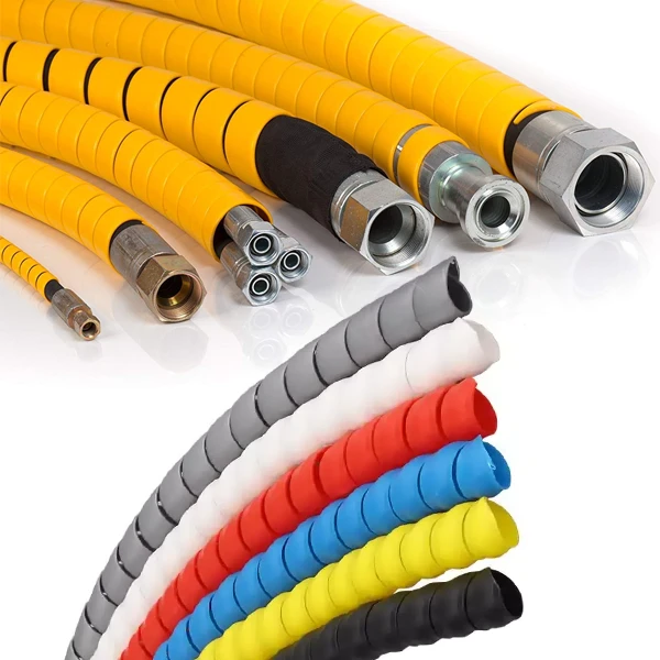
Cover selection should therefore account for abrasion, ozone, sunlight, oil splash, weather, heat, and contact with nearby structures. Where rubbing cannot be removed by routing, hydraulic hose protection can be used around exposed sections to reduce direct abrasion and contact damage. Protection should not force the hose below its minimum bend radius or trap it against a hot surface.
Bend radius matters because reinforcement is designed to carry pressure in a controlled geometry. Pulling a hose into a radius tighter than the manufacturer’s minimum can distort braid or spiral layers, narrow the bore, and concentrate stress near the fittings. Repeated flexing makes poor routing more serious: 10,000 bending cycles at one tight location create a different condition from a stationary hose that moves twice per month.
Hose length should allow movement without tension but should not leave large loops on the floor. A 3 m connection may need additional length when equipment travels 0.5 m, yet adding another 3 m without a routing reason increases weight, pressure loss, abrasion area, and handling effort. Keep bends away from the fitting whenever the installation permits it.
Couplings need the same level of attention. Cam-and-groove fittings, flanges, threaded ends, dry-disconnect couplings, and other transfer connections have different pressure ratings, sealing materials, retention methods, and electrical characteristics. A fuel-compatible hose paired with an incompatible gasket can still leak after the seal swells or hardens.
Check at least six assembly details before purchase:
-
hose and stem dimensional compatibility;
-
coupling material for the transferred fluid;
-
gasket compound and fuel blend compatibility;
-
fitting working-pressure rating;
-
crimp, swage, clamp, or other approved attachment method;
-
electrical continuity where the service requires it.
The fitting attachment should normally come from a validated hose-and-coupling system. Mixing a hose from one manufacturer with an unrelated ferrule and stem may produce dimensions that appear correct but lack tested retention data. SAE J517 has contained assembly-level pressure requirements for decades, including its 2017 and 2020 revisions, because connector limitations are part of hose performance rather than a separate purchasing issue.
Inspection requirements should be planned before the first day of service. Record the hose identification, installation date, fluid, pressure rating, fitting type, and any pressure or continuity test results. For a fleet with 100 transfer hoses, individual records allow damaged assemblies to be removed based on condition and service history instead of relying on memory.
Look for cover cuts, cracking, flattened sections, blistering, soft areas, exposed reinforcement, coupling movement, leakage, permanent kinks, and unusually stiff sections. Inspection frequency should reflect use: a hose handled 50 times per week needs a different inspection schedule from a fixed hose used once each month.
Pressure tests and electrical continuity tests should follow the hose manufacturer or applicable industry procedure. Repeatedly applying an arbitrary pressure simply because it is below the printed burst rating can damage an aged assembly. A hose that has suffered vehicle crushing, severe kinking, fire exposure, or coupling displacement also requires more than a surface check.
For purchasing, a usable request can be written in one compact specification:
| Field | Example requirement |
|---|---|
| Medium | B20 diesel, up to 20% biodiesel |
| Service | Suction and discharge |
| Inside diameter | 50 mm |
| Length | 8 m |
| Working pressure | 10 bar |
| Maximum fluid temperature | 60°C |
| Ambient range | -20°C to +45°C |
| Flow | 300 L/min |
| Location | Outdoor mobile transfer |
| Cover | Oil, weather, ozone, and abrasion resistant |
| Electrical requirement | Conductive assembly where specified |
| Ends | Fuel-compatible industrial couplings |
Providing all 11 fields gives a supplier enough information to compare tube compound, reinforcement, cover, fittings, vacuum performance, and operating limits together. Ordering only “a 2-inch fuel hose” leaves chemical blend, 10-bar pressure, 20% biodiesel content, temperature, suction duty, electrical requirement, and fitting rating unspecified—precisely the information used to determine whether the assembled hose is suitable for the transfer system.