RS485 Control and Encoder Planning for a Flat Direct Drive Motor
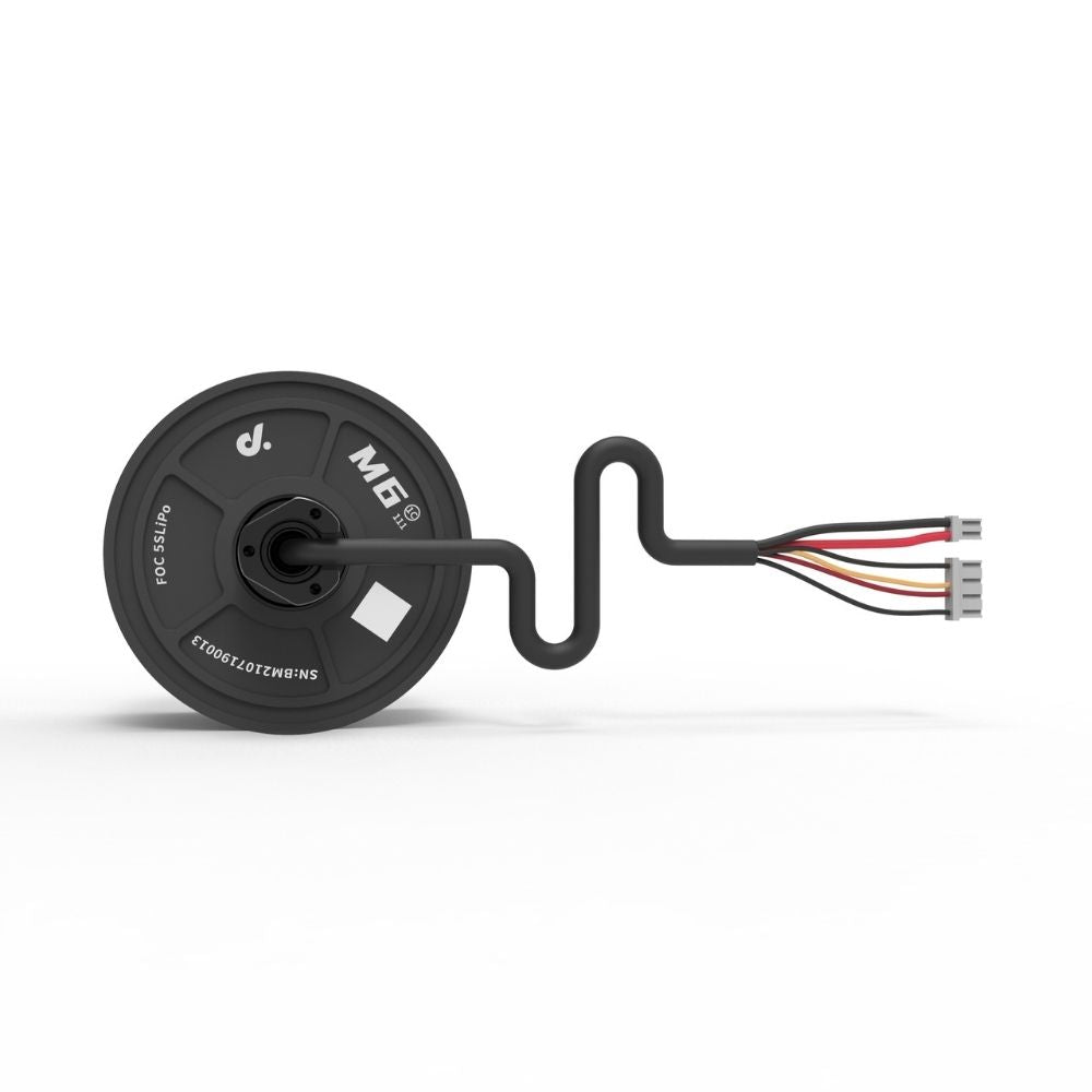
RS485 control and encoder planning determine how efficiently a flat direct drive motor performs in robotic and automation systems. A well-designed RS485 network can support 10–32 motor nodes, communication distances above 100 meters, and stable data rates from 115200 bps to 1 Mbps. Encoder selection with 14–20 bit resolution enables angular accuracy from 0.022° to 0.00034°, supporting precise motion control in compact platforms.
Flat direct drive motors require accurate feedback because the motor output shaft is directly connected to the mechanical load without a gearbox. Traditional geared systems can hide small position errors through transmission reduction, while direct drive systems expose every control adjustment to the load. A motor running at 300 rpm with a 16-bit encoder receives 65536 position points per revolution, allowing the controller to measure movement changes below 0.006 degrees.
The communication system must provide stable information exchange between the motor controller and the host computer. RS485 is commonly selected because differential signaling reduces interference from nearby power electronics and motor switching circuits.
“A properly configured RS485 bus can maintain reliable communication across 50–100 meter cable lengths while supporting multiple motor controllers on the same network.”
A typical RS485 motor network contains a master controller and several slave motor units. Each motor receives commands such as position, velocity, and torque targets while returning encoder position, temperature, and diagnostic information.
| Communication Item | Typical Range |
|---|---|
| Baud rate | 115200 bps–1 Mbps |
| Maximum nodes | 16–32 devices |
| Cable distance | 50–120 meters |
| Update frequency | 100–1000 Hz |
For mobile robots and compact automation equipment developed after 2015, distributed motor control became more common because systems required more wheels, joints, and sensors inside limited installation spaces. A single RS485 bus can reduce cable quantity by approximately 30–50% compared with separate point-to-point wiring designs.
The reduced wiring approach also requires careful encoder planning because communication quality depends on accurate feedback data. Encoder systems determine how the controller measures position, speed, and acceleration.
Incremental encoders remain popular because of their low cost and high rotational speed capability. Absolute encoders are preferred in systems that require immediate position recovery after power loss. Magnetic encoders are often selected for flat motor structures because they occupy less space than many optical encoder assemblies.
| Encoder Type | Resolution Range | Typical Application |
|---|---|---|
| Incremental | 1000–10000 CPR | Speed control |
| Magnetic absolute | 12–20 bit | Robotics |
| Optical absolute | 16–24 bit | Precision positioning |
A flat motor design such as the M0602C-112 direct drive motor requires encoder feedback that matches the mechanical accuracy requirement. When the motor is installed in a robot wheel, even a small angle error can accumulate during navigation. For example, a 0.1° measurement error repeated over a 500 mm wheel circumference can create approximately 0.87 mm positional deviation per revolution.
Encoder resolution should also match the controller sampling rate. Increasing encoder resolution without improving control frequency may not provide additional motion accuracy.
A practical control system often uses different update rates for different functions:
| Control Function | Typical Frequency |
|---|---|
| Current loop | 5–20 kHz |
| Velocity loop | 500–2000 Hz |
| Position loop | 100–500 Hz |
| RS485 communication | 50–1000 Hz |
This layered control structure allows the motor driver to process fast electrical changes locally while exchanging higher-level commands through RS485. In systems operating continuously for 8–12 hours per day, separating internal control from external communication improves stability.
“The motor driver should process encoder feedback locally instead of sending every encoder pulse through the communication network.”
Noise control becomes important when the motor and encoder cables are installed near switching power supplies or high-current wiring. RS485 uses twisted differential pairs, which helps reduce common-mode interference.
Recommended wiring practices include:
| Design Method | Purpose |
|---|---|
| Twisted pair cable | Reduce electromagnetic interference |
| 120 Ω termination resistor | Prevent signal reflection |
| Shielded cable | Improve noise resistance |
| Short signal paths | Maintain encoder quality |
In industrial environments, incorrect termination can create communication errors. A 120 Ω resistor is normally installed at both ends of a long RS485 bus. Without proper termination, signal reflection may increase data errors, especially when communication speeds exceed 500 kbps.
Encoder signal quality also affects low-speed movement. Direct drive motors are often used in robots that require smooth movement at walking speed or slower. A low-resolution encoder may cause uneven velocity estimation because the controller receives fewer position changes during slow rotation.
For example, a 12-bit encoder provides 4096 counts per revolution. A 20-bit encoder provides 1048576 counts per revolution. The higher-resolution device offers 256 times more position information, which improves low-speed regulation.
Multi-axis systems require synchronization between several direct drive motors. Autonomous robots, robotic arms, and inspection platforms may use 4–12 motor axes operating together.
A synchronized system usually compares target and feedback position:
[
Position\ Error = Target\ Position - Encoder\ Position
]
The controller then adjusts motor current to reduce the difference. This process occurs hundreds or thousands of times per second depending on the application.
| System Type | Number of Motors | Typical Feedback Requirement |
|---|---|---|
| Mobile robot | 2–6 | Speed and position control |
| Robot arm | 6–12 | High precision positioning |
| Automated equipment | 4–20 | Coordinated movement |
Thermal conditions also influence encoder and communication reliability. Motor temperatures may rise by 40–80°C during continuous operation depending on current level, cooling method, and installation space. Temperature sensors integrated into motor drivers allow the controller to reduce output when operating conditions exceed the rated range.
A compact motor housing creates limited space for heat dissipation, so electrical efficiency becomes important. Reducing copper losses and improving current control can lower temperature rise by 10–20% in some optimized designs.
The selection of RS485 protocol settings, encoder resolution, and motor controller architecture should be considered together during system development. A communication interface with insufficient update speed may limit the benefits of a high-resolution encoder, while an advanced encoder cannot compensate for poor wiring or unstable control timing.
“Reliable motion performance comes from matching communication speed, encoder resolution, controller frequency, and mechanical requirements.”
Flat direct drive motors used in modern robotic equipment depend on this balance. With appropriate RS485 planning and encoder integration, systems can achieve repeatable positioning, smoother operation, and longer service periods in applications ranging from autonomous vehicles to precision automation platforms.